sábado, 24 de maio de 2014

Motion and Touch Controlled Guitar


Check out part 1 and 2 to get an understanding of what this project is about. this project is near complete and includes basic effects such as Reverb, delay as well as motion controled pitch shifting and granular synthesis capabilities.

This music is very experimental and each part was done in one take so there are mistakes along the way but I hope it gives you an idea of what my Max MSP program is capable of.

The Karman Faders - Audio Interface - Max/MSP/Jitter


A short in-development demo of an intangible interface for sound control. A version of this patch was exhibited at Ffotogallery, Cardiff as part of the Vision On: New Media and Sound Season 09.

Download the free Application from here - http://www.switchdialogue.co.uk/jthomas

Photos here: http://www.flickr.com/photos/switchbo...

This project was made in Max/MSP and Jitter using the cv.jit objects


Type 40 Mark III: Interactive Sound Sculpture


https://vimeo.com/64119774

Appearing at the Austin Mini Maker Faire: May 5, 2013.
Is it a time machine? A MIDI controller? An art sculpture? Yes! We just call it awesome. The Type 40 Mark III console is an interactive sound sculpture. The console surface is covered interactive controls that trigger samples, loops, and other sounds. You can also modify tempo, tone, pitch, and apply different sound filters. We invite you to explore and play - create your own dynamic soundscape!
Project leads Steve Noreyko, Dr. John Edwards, and Andrea Swehosky have decades of experience hacking, building, and designing.

Spider Bark- Steven White sound sculpture


Artist Steven White reconstructs obsolete technology, in this case a combine harvester to produce interactive kinetic sound sculpture. The artwork explores issues of technological evolution and devolution, the global economy and it's impact on local landscape. Taking five years to complete, this body of work reflects a playful sense of wonder at the possibilities present with these fragments of technology. The interactive nature of the sculptures engages the viewer in a playful dance; cranks get rotated, sounds are produced and the individuals role in these complex webs is highlighted.


http://www.stevenwhite.ca

„ between truth & lies" interactive sound sculpture by Roll Weiland


interactive soundinstallation in the castle of Larochette (Luxembourg) 2010.
by Roll Weiland.

Trigger sounds by moving your hands in front of the 6 spheres ( = 6 sensors).
A phrase will follow the sound immediately if you then keep your hand still.
The spoken phrases are in English, German and French.

segunda-feira, 19 de maio de 2014

Esquema FlexiForce Sensor

Introduction

This is a quick how-to explaining everything you need to get started using your Flexiforce Pressure Sensor.  This example uses the 25lb version, but the concepts learned apply to all the Flex sensors.
Flexiforce

Requirements

Necessary hardware to follow this guide:
You'll also need the Arduino IDE for programming.

Hardware

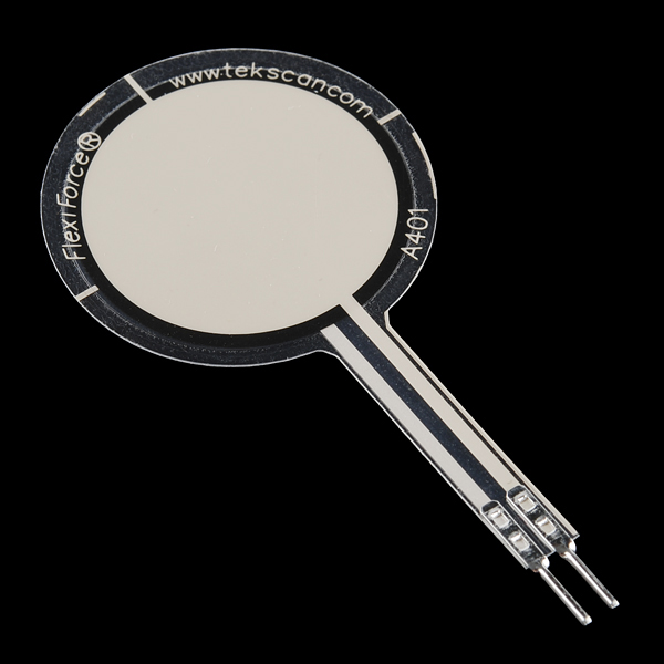
The Flexiforce Pressure Sensor is essentially a variable resistor. When no pressure is applied, the resistance between the two outer leads is incredibly large, probably greater than 10 Mega Ohms (more than my meter can measure). When pressure is applied, the resistance measured between the outer leads lowers until you've reached the max pressure it's intended to measure. In this case that's about 25 lbs of pressure, and the current Flexiforce Pressure sensor I'm using measures about 50K Ohms when given that max amount of pressure.
You can test the range of your sensor using a multimeter. Just attach the two outer leads to the multimeter and set the meter to measure resistance. Then squeeze the sensor and watch the resistance value change.
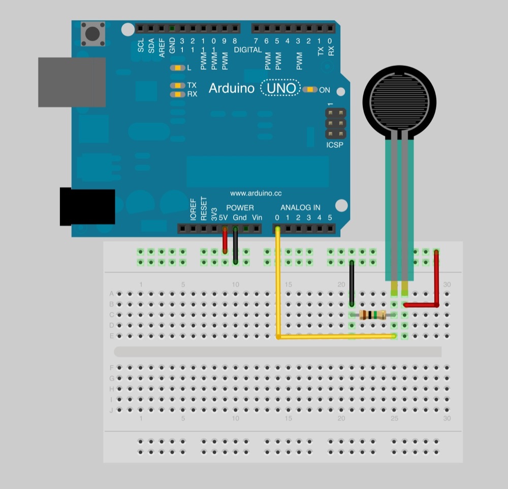
Now, let's read values with an Arduino. To do this, we create a voltage divider circuit with the Flexiforce sensor and an extra resistor. I picked 1M Ohm in this example because it's about in the middle of the Flexiforce sensor's dynamic range. Many other similar values could work as well.
Connect 5V to one side of the voltage divider, and GND to the other. In the middle, where the Flexiforce sensor and the resistor connect, connect one of the analog-in pins of the Arduino with a jumper wire. In this case I used pin A0. Here is a Fritzing diagram of the setup:
alt text
Fritzing Wiring Diagram
*Note*: The sensor in the image doesn't look exactly the same as the Flexiforce sensor, but very close. The actual Flexiforce sensor has a larger surface area.

Software

Now that you have your circuit wired and ready, it's time to write some very basic Arduino code.  This code is almost exactly the same as Arduino's standard AnalogReadSerial example. Let's take a look to see what it's doing:
     
// Flexiforce quick start example
// Reads A0 every 100ms and sends voltage value over serial

void setup() 
{
  // Start serial at 9600 baud
  Serial.begin(9600); 
}

    void loop() 
{
  // Read the input on analog pin 0:
  int sensorValue = analogRead(A0);
  
  // Convert the analog reading (which goes from 0 - 1023) to a voltage (0 - 5V):
  float voltage = sensorValue * (5.0 / 1023.0);
  
  // Print out the value you read:
  Serial.println(voltage);
  
  // Wait 100 milliseconds
  delay(100);
}

The code is simply running in a small infinite loop every 100ms, or 10 times a second. In each pass through the loop, it measures the voltage on pin A0 and returns a corresponding value between 0 and 1023. 0 represents ground in this case and 1023 indicates A0 is sitting at 5 Volts. For other numbers in between, we can figure out the voltage by multiplying the measured number by the fraction, 5.0 / 1023.0. We then spit this value back over the Serial port, we can watch the values change in real time.
Go ahead and try. Make sure you have the hardware connected correctly. Program the Arduino, open up the Arduino Serial Monitor (make sure it's using 9600 baud), and watch the voltage values change as you press and release the Flexiforce Pressure Sensor.

Conclusion

Now you know how to use the Flexiforce Pressure Sensor. Believe it or not, there are many different analog sensors where you can use what you learned here and collect data the exact same way. Now it's all up to you to use these types of products however you imagine. If you have any other questions or comments, please drop them in the box below. Enjoy!


https://www.sparkfun.com/tutorials/389

Arduino Circuits


Ultrasonic sensor


The following code outputs the distance:
  1. #define echoPin 11 // Echo Pin
  2. #define trigPin 12 // Trigger Pin
  3. long duration, distance; // Duration used to calculate distance
  4. void setup() {
  5.  Serial.begin (9600);
  6.  pinMode(trigPin, OUTPUT);
  7.  pinMode(echoPin, INPUT);
  8. }
  9. void loop() {
  10.  digitalWrite(trigPin, LOW);
  11.  delayMicroseconds(2);
  12.  digitalWrite(trigPin, HIGH);
  13.  delayMicroseconds(10);
  14.  digitalWrite(trigPin, LOW);
  15.  duration = pulseIn(echoPin, HIGH);
  16.  //Calculate the distance (in cm) based on the speed of sound.
  17.  distance = duration/58.2;
  18.  Serial.println(distance);
  19.  delay(50);
  20. }

Photoresistor controlling LED

With a photo resistor you can control something from your Arduino board depending on light intake. The following circuit shows how to connect your photo resistor to the Arduino board and read the values.

  1. int ledPin = 3;
  2. int photocellInput = 0;
  3. void setup()  {
  4.   pinMode(ledPin, OUTPUT);
  5. }
  6. void loop()  {
  7.   photocellInput = (analogRead(0)/4); // Divides input 0-1023 to resemble to 0-255
  8.   analogWrite(ledPin, photocellInput);  
  9.   // The delay can be change to get the desired dimming effect
  10.   delay(20);                            
  11. }

Decision maker with LEDs

The following circuit and code shows an example of a decision maker made with LEDs. Pushing the button will make the LEDs flash in a random order for 1 second. Then displaying the random decision where one LED lights up for 3 seconds and then reseting.

  1. int timeShowRandom = 1000;
  2. int timeShowDecision = 3000;
  3. int timeBlink = 50;
  4. int buttonPin = 3;
  5. int buttonPress = false;
  6. int randomNumber;
  7. int previousNo = 0;
  8. int timePassed = 0;
  9. void setup() {    
  10.   // Set button pin
  11.   pinMode(buttonPin, INPUT);
  12.   // Set output pins  
  13.   pinMode(12, OUTPUT);
  14.   pinMode(11, OUTPUT);
  15.   pinMode(10, OUTPUT);
  16. }
  17. void getRandomNo() {
  18.   int rand = random(10,13);
  19.   if(rand == previousNo) {
  20.     getRandomNo();
  21.   } else {
  22.     randomNumber = rand;
  23.     previousNo = randomNumber;
  24.   }
  25. }
  26. void loop() {
  27.   // Check if button is pressed
  28.   if(digitalRead(buttonPin) == HIGH && buttonPress == false) {
  29.      buttonPress = true;
  30.   } if(buttonPress == true && timePassed <= timeShowRandom) {
  31.     getRandomNo(); // Get random pin number
  32.     digitalWrite(randomNumber, HIGH);
  33.     delay(timeBlink);  
  34.     digitalWrite(randomNumber, LOW);
  35.     delay(timeBlink);  
  36.     timePassed = timePassed + (timeBlink * 2);
  37.   } else if(buttonPress == true) {
  38.     digitalWrite(random(10,13), HIGH); // Set random pin on
  39.     delay(timeShowDecision); // For x seconds
  40.     buttonPress = false; // Set button to be enabled again
  41.     timePassed = 0;
  42.   } else {
  43.     // Reset all output pins
  44.     digitalWrite(10, LOW);
  45.     digitalWrite(11, LOW);
  46.     digitalWrite(12, LOW);
  47.   }    
  48. }

Arduino Ethernet Shield hooked up to LED message display

This hack allows you to display messages to a standard Amplus LED Message Display from Clas Ohlsson. The display is controlled by a remote control and via a RJ14 cable plugged into the screen. Serial data is transmitted from cable to the screen. The LED Message display expects the message you pass to it to be encrypted with a check sum. With the help of Rasmus blog post I could generate this checksum in Arduino. I turned his Perl code into Arduino code that you can see below.

  1. int stringToInt(String thisString) {
  2.   String letters = " !’#$%&’()*+,-./0123456789:;<=>?@ABCDEFGHIJKLMNOPQRSTUVWXYZ[/]^_`abcdefghijklmnopqrstuvwxyz{|}~";
  3.  
  4.   int newstr = 32 + letters.indexOf(thisString);
  5.  
  6.   return newstr;
  7. }
  8. String generateMessage(String inputString) {
  9.  
  10.   byte checksum = 0×74;
  11.   int i;
  12.  
  13.   for(i = 0;i < inputString.length();i++) {
  14.       String currentChar    = inputString.substring(i,i+1);
  15.       int asciiChar         = stringToInt(currentChar);
  16.       checksum = checksum ^ asciiChar;
  17.   }
  18.  
  19.    String hexStr =  String(checksum, HEX);
  20.    hexStr.toUpperCase();
  21.    
  22.    String message = "<ID00><L1><PA><FE><MA><WC><FE>" + inputString + hexStr + "<E>";
  23.    return message;
  24.    
  25. }
  26. String myString = "My led display message here";
  27.  String mess = generateMessage(myString);
  28.   Serial.print(mess);
Download my Arduino library on Github to try this out.

Control servo motor


The servo motor can be controlled by using the servo library(Servo.h) in Arduino IDE. Plug in the control wire of the servo motor into one of the PWM pins. Attach the servo object to that pin.
  1. Servo servoMotor;
  2. servoMotor.attach(9);
To rotate the servo motor pass in a number between 0 and 180. The servo motor can only move up to 180 degrees.
  1. myservo.write(90);
  2. delay(2000);
  3. myservo.write(180);
  4. delay(2000);

Using a potentiometer to control LED


You can easly control the current running through your LED by adding a potentiometer as part of your circuit.

To control the LED with Arduino programming you attach the potentiometer to your analog in and let your Arduino program decide how much to dim the LED depending on the input you get from the potentiometer.

The input from analogRead returns a value between 0 and 1023. The analogWrite takes values between 0 and 255. The code below show you have to convert your analog in value to make your LED shine as bright as possible when the potentiometer is fully on.
  1. int ledPin = 3;
  2. int potentiomenterInput = 0;
  3. void setup()  {
  4.   pinMode(ledPin, OUTPUT);
  5. }
  6. void loop()  {
  7.  
  8.   potentiomenterInput = (analogRead(0)/4); // Divides input 0-1023 to resemble to 0-255
  9.   analogWrite(ledPin, potentiomenterInput);  
  10.   // The delay can be change to get the desired dimming effect
  11.   delay(20);                            

domingo, 11 de maio de 2014

Arduino 5 Minute Tutorials: Lesson 5 – Servo Motors

Lessons Menu:

Lesson 5 Hardware:

  1. Computer / Laptop or Netbook
  2. Arduino Microcontroller
  3. USB to Serial Adapter (if your microcontroller does not have a USB port)
  4. Appropriate USB cable (Arduino boards draw power from the USB port – no batteries yet)
  5. Standard servo motor (current consumption <50mA)
  6. Pin headers / cables

Controlling a servo motor directly from the Arduino is quite easy. However, a servo motor may require significantly more current than the Arduino can provide. The following example uses a standard sized servo (without any load) powered directly from the Arduino via USB. When powering the servo directly from the Arduino board:
  1. Connect the black wire from the servo to the GND pin on the Arduino
  2. Connect the red wire from the servo to the +5V pin on the Arduino
  3. Connect the yellow or white wire from the servo to a digital pin on the Arduino

Arduino 5 Minute Tutorials
Alternatively, you can plug the servo’s wire into three adjacent pins, and set the pin connected to the red lead to “HIGH” and the pin connected to the black lead to “LOW”. If you want to use a more powerful servo, or if you want to connect it to a separate power supply, you would connect the battery / power supply’s red (5V) and black (GND) wires to the servo’s red and black wires, and connect the signal wire to the Arduino. Note that you also need to connect the batter’s GND line to the Arduino’s GND pins (“common ground”).
Arduino 5 Minute Tutorials
pinMode(pin number, OUTPUT);
This sets a pin number as dedicated input or output. In this case, we called the pin “servopin” and assigned it a value of 4. The term “pulse” is in black as it is not a reserved word and can be changed by the user. It is best to use descriptive variables when coding to understand what each does, or the information it will contain. Servos operate by sending a timed +5V pulse (usually between 500us and 2500us) to the onboard electronics, which is repeated every ~20ms. This pulse corresponds to a servo position, usually from 0 to 180 degrees.
  • 5V for 500 microseconds = 0.5 milliseconds and corresponds to 0 degrees
  • 5V for 1500 microseconds = 1.5 milliseconds and corresponds to 90 degrees
  • 5V for 2500 microseconds = 2.5 milliseconds and corresponds to 180 degrees
  • The relationship is linear, so use mathematics to determine the pulse which corresponds to a given angle. Note that if you send a signal that is greater or lower than the servo can accept (for example, Firgelli linear actuators accept 1 to 2 ms), you might damage the actuator.
Another option for controlling servos is to use the Arduino “servo library” (previously separate from the basic Arduino software, it is now included with V1.0). The servo library manages much of the overhead and includes new, custom commands. If you want to control multiple servo motors, you should use a servo motor controller and a separate power supply between 4.8V to 6V.


Arduino 5 Minute Tutorials: Lesson 6 – Force, Bend, Stretch Sensors

http://www.robotshop.com/blog/en/arduino-5-minute-tutorials-lesson-6-force-bend-stretch-sensors-3635


Lessons Menu:

Lesson 6 Hardware:

  1. Computer / Laptop or Netbook
  2. Arduino Microcontroller
  3. USB to Serial Adapter (if your microcontroller does not have a USB port)
  4. Appropriate USB cable (Arduino boards draw power from the USB port – no batteries yet)
  5. Standard servo motor (current consumption <50mA)
  6. Pin headers / cables
  7. Bend /stretch sensor and/ or Force sensor

Force “sensors” are actually “force sensing resistors” (FSRs). Similarly, bend “sensors” are actually products whose resistance changes with flexing. These can all be categorized as “variable resistors”. To interface a product whose resistance changes with a microcontroller, you need a voltage divider circuit. This “circuit” is nothing complex – aside from wires, the only part you are missing is a resistor.
To create the circuit, add the variable resistor in series with a similar (standard) resistor of roughly the same resistance (in ohms). Connect a wire between the two – this wire goes to the analog input of the board. There should only be two wires left – one end of the standard resistor, and one end from the variable resistor – these ends are connected to +5V and GND respectively. You can now use it as a regular sensor with analog output.
Arduino 5 Minute Tutorials
If you want a pre-made circuit, consider the Phidgets voltage divider:
Arduino 5 Minute Tutorials
The output of this “mini circuit” is a signal between 0 to 5V (this is referred to as an analog signal), which is connected to an analog pin of the microcontroller. The microcontroller’s on-board analog to digital converter (ADC) interprets this voltage and assigns it a number which you can use in your code. For 10 bit ADC (210), you will get a number between 0 and 1024 representing 0V to 5V. You would need an equation in your code to use this number to send the appropriate signal to a motor controller. As you might have suspected, the code is now identical to that used to get an analog input.
To get sample code, open the Arduino software and go to File -> Examples -> Analog -> AnalogInOutSerial
The video above shows a bend sensor connected to an Arduino, and the Arduino is connected to a small servo motor. The analog value associated with the flex sensor is read by the Arduino, and that value is converted to a rough position. You would merge the Analog example code with the servo code, and add a single line to convert the 0 to 1024 value to 0 to 180 degrees. It is easy to see how, with many of these sensors, you can create a data glove which controls a robotic hand.


Force Sensitive Resistor (FSR)

https://learn.adafruit.com/force-sensitive-resistor-fsr

Chord Painter - Max/MSP Visualization Patch


The goal of this project was to explore the possibilities of visualizing musical structure and the relations between color and sound. I am interested in synaesthesia and enjoy analyzing musical structure, which led to my interest in creating something that could translate chord combinations into some kind of visual medium.

Built the Max/MSP + Jitter programming environment, the chordpainter is a customizable software patch that creates images based on the chords the user plays on a MIDI-based instrument. Utilizing artificial tango's at.chord object for MIDI chord recognition, I mapped chord values to color combinations, photo layering effects, and video, producing a real-time visual complement to the audio. The chordpainter can be used as both a performance medium or a tool for teaching and understanding chord structure relations.

Requires the artificial tango library. Image content courtesy of gettyimages inc.

Analogue sensors with Max/MSP using OSC over WiFi


Work in progress. Quick demo showing triple-axis gyroscope and light sensor attached to analogue inputs to stream sensor data via WiFi to Max/MSP as OSC messages. Max patch uses sensor data used to control parameters of synth.