sexta-feira, 3 de outubro de 2014
sábado, 24 de maio de 2014
Motion and Touch Controlled Guitar
Check out part 1 and 2 to get an understanding of what this project is about. this project is near complete and includes basic effects such as Reverb, delay as well as motion controled pitch shifting and granular synthesis capabilities.
This music is very experimental and each part was done in one take so there are mistakes along the way but I hope it gives you an idea of what my Max MSP program is capable of.

Type 40 Mark III: Interactive Sound Sculpture

https://vimeo.com/64119774
Appearing at the Austin Mini Maker Faire: May 5, 2013.
Is it a time machine? A MIDI controller? An art sculpture? Yes! We just call it awesome. The Type 40 Mark III console is an interactive sound sculpture. The console surface is covered interactive controls that trigger samples, loops, and other sounds. You can also modify tempo, tone, pitch, and apply different sound filters. We invite you to explore and play - create your own dynamic soundscape!
Project leads Steve Noreyko, Dr. John Edwards, and Andrea Swehosky have decades of experience hacking, building, and designing.
Spider Bark- Steven White sound sculpture
Artist Steven White reconstructs obsolete technology, in this case a combine harvester to produce interactive kinetic sound sculpture. The artwork explores issues of technological evolution and devolution, the global economy and it's impact on local landscape. Taking five years to complete, this body of work reflects a playful sense of wonder at the possibilities present with these fragments of technology. The interactive nature of the sculptures engages the viewer in a playful dance; cranks get rotated, sounds are produced and the individuals role in these complex webs is highlighted.
http://www.stevenwhite.ca
„ between truth & lies" interactive sound sculpture by Roll Weiland
interactive soundinstallation in the castle of Larochette (Luxembourg) 2010.
by Roll Weiland.
Trigger sounds by moving your hands in front of the 6 spheres ( = 6 sensors).
A phrase will follow the sound immediately if you then keep your hand still.
The spoken phrases are in English, German and French.
segunda-feira, 19 de maio de 2014
Esquema FlexiForce Sensor
Introduction
This is a quick how-to explaining everything you need to get started using your Flexiforce Pressure Sensor. This example uses the 25lb version, but the concepts learned apply to all the Flex sensors.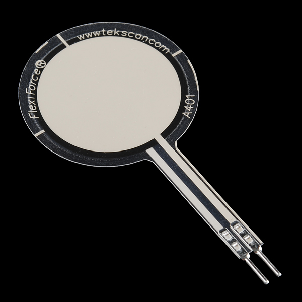
Requirements
Necessary hardware to follow this guide:- Arduino UNO or other Arduino compatible board (e.g. Pro Micro)
- Flexiforce Pressure Sensor
- Breadboard
- M/M Jumper Wires
- 1 MegaOhm Resistor (part of our Resistor Kit)
Hardware
The Flexiforce Pressure Sensor is essentially a variable resistor. When no pressure is applied, the resistance between the two outer leads is incredibly large, probably greater than 10 Mega Ohms (more than my meter can measure). When pressure is applied, the resistance measured between the outer leads lowers until you've reached the max pressure it's intended to measure. In this case that's about 25 lbs of pressure, and the current Flexiforce Pressure sensor I'm using measures about 50K Ohms when given that max amount of pressure.You can test the range of your sensor using a multimeter. Just attach the two outer leads to the multimeter and set the meter to measure resistance. Then squeeze the sensor and watch the resistance value change.
Now, let's read values with an Arduino. To do this, we create a voltage divider circuit with the Flexiforce sensor and an extra resistor. I picked 1M Ohm in this example because it's about in the middle of the Flexiforce sensor's dynamic range. Many other similar values could work as well.
Connect 5V to one side of the voltage divider, and GND to the other. In the middle, where the Flexiforce sensor and the resistor connect, connect one of the analog-in pins of the Arduino with a jumper wire. In this case I used pin A0. Here is a Fritzing diagram of the setup:
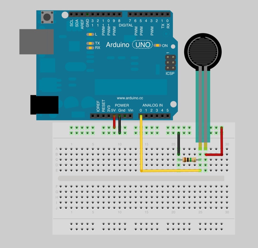
Fritzing Wiring Diagram
Software
Now that you have your circuit wired and ready, it's time to write some very basic Arduino code. This code is almost exactly the same as Arduino's standard AnalogReadSerial example. Let's take a look to see what it's doing:// Flexiforce quick start example // Reads A0 every 100ms and sends voltage value over serial void setup() { // Start serial at 9600 baud Serial.begin(9600); }
    void loop()
{
  // Read the input on analog pin 0:
  int sensorValue = analogRead(A0);

  // Convert the analog reading (which goes from 0 - 1023) to a voltage (0 - 5V):
  float voltage = sensorValue * (5.0 / 1023.0);

  // Print out the value you read:
  Serial.println(voltage);

  // Wait 100 milliseconds
  delay(100);
}
Go ahead and try. Make sure you have the hardware connected correctly. Program the Arduino, open up the Arduino Serial Monitor (make sure it's using 9600 baud), and watch the voltage values change as you press and release the Flexiforce Pressure Sensor.
Conclusion
Now you know how to use the Flexiforce Pressure Sensor. Believe it or not, there are many different analog sensors where you can use what you learned here and collect data the exact same way. Now it's all up to you to use these types of products however you imagine. If you have any other questions or comments, please drop them in the box below. Enjoy!https://www.sparkfun.com/tutorials/389
Subscrever:
Mensagens (Atom)